ECUs can be a complex subject. To cover this topic at any great depth is beyond the scope of this site.
So the object will be to provide an overview of ECU functionality, how it interconnects to the rest of the helicopter, along with some hints for resolving specific problems.
Hopefully this will give you enough information to at least eliminate whether you have an ECU problem, or whether your problem lies more with sensors or other devices external to the ECU.
At this time, 3 ECUs will be described in this section. They are the 162F ECU, the MEFI-4B used in the Talon and the GoTech ProX used in the VP engine. I will add more in the future if they become common in Rotorways.
162F ECU
The 162F ECUs were built by Syntronix Corporation of Tempe, Arizona. These ECUs were designed for the Rotorway helicopter and the firmware was written specifically for the 162F.
The 162F ECUs are designed to operate as a primary/secondary pair and have extensive strategies to handle numerous failure modes of the ECUs or of any ancillary sensors.
While these ECUs are getting to be somewhat older technology, they are a well designed unit and are still very capable and reliable.
162F ECU Operation
The ECUs operate as a primary/secondary pair. The ECUs communicate with each other via signaling lines and via a serial data link. While the engine is running on the primary ECU, the secondary ECU is fully operational. The secondary ECU is inhibited from injecting fuel by a signaling line from the primary ECU. If this signal line de-asserts due to the primary ECU failing or due to the primary ECU electing to pass control to the secondary ECU, the secondary ECU will immediately begin injecting fuel.
While the engine is running on the primary ECU, the secondary ECU is continuously sending TPS and BARO data to the primary ECU via the serial data link. This allows the primary ECU to continue operating if it's TPS or BARO has failed by using the TPS or BARO data from the secondary ECU. The primary ECU may or may not use this data, it has numerous other failure strategies it may elect to use instead.
The 162F ECUs operate in what is known as alpha-N mode. This means that the volume of air through the engine is determined by the throttle position and the RPM. While the primary ECU does have a MAP sensor, it is almost never used except if the primary ECU is unable to switch to the secondary ECU (ie. it's not operational) and the primary TPS has failed. It will then use the MAP sensor, which has it's own fuel table.
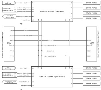
162F Ignition System
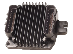
The 162F uses ignition packs from an early 90's Saturn car. These ignition packs run stand-alone and will work even when the ECUs are turned off. The ignition pack has it's own built-in spark advance curve. This advance curve can be over-ridden by a signal from the ECU. If the ignition pack fails to recieve a timing signal from the ECU, it will revert to it's built in advance curve. This actually happens when running on the secondary ECU, only the primary ECU over-rides the built-in advance curve, the secondary ECU doesn't send a timing signal and instead relies on the built-in advance curve.
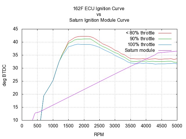
Ignition Advance Curves
Each ignition pack sends timing signals to both ECUs, and each ECU receives 2 timing signals, one from each ignition pack. This means that an ignition pack is not tied to a specific ECU. So long as one of the ignition packs is operational, either ECU can run.
162F Fuel Tables
In order for the ECU to calculate how much fuel to inject, it first has to know how much air, by weight, is going through the engine. It then can inject the appropriate amount of fuel to give about a 12.5:1 air to fuel ratio.
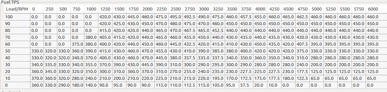
Example 162F Fuel Table
To calculate the mass (or weight) of the air through the engine, the ECU first determines the volume of air going through the engine. It does this by taking the current throttle position and the RPM of the engine, and simply looking it up in a fuel table (sometimes referred to as a volumetric efficiency or VE table). Above is an example of this fuel table.
The values in the fuel table are usually dimensionless, although I believe the 162F fuel tables are in microseconds of injector time at standard pressure and temperature. But I haven't verified this yet.
Now that the ECU knows the volume of air from the fuel table, it calculates the mass (or density) of the air by multiplying the volume of air by the pressure (BARO sensor) and temperature (intake air temp). Once the ECU knows the mass of the air going through the engine, it's a simple matter to determine how much fuel to inject.
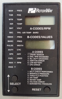
162F Diagnostics
The FADEC display is a good place to start when diagnosing many ECU problems. The FADEC display will show you the current output of all the sensors along with some of the ECU calculated values.
abd this is a test
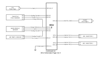
162F ECU Wiring Harness Diagrams
162F Engine Wiring Harness
162F Repair
While these ECUs are generally quite reliable, like any electronic device, failures can happen. By far, the most common failures are the result of external problems such as the main battery being connected up backwards, and other ground fault issues. Very infrequently, a component within the ECU will fail on it's own.
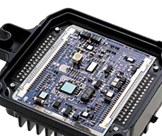
These ECUs are constructed of standard 4-layer PCB boards with surface mount components. Most of the components are either still available or I have spares in stock, allowing most ECU failures to be repaired.
162F Programming
The fuel tables, ignition tables and parameter tables are stored in flash memory, and are programmable with an external programmer. The programmer communicates with the ECU via an RS-232 serial connection. But this serial connection is not brought out in the engine wiring harness, so either a modification to the wiring harness is required to program the ECUs while installed, or a special plug can be used if programming on the bench.
162F Recommended Fixes and Enhancements
Under construction
More to come
Talon ECU
The Talon uses the MEFI-4B ECU built by GM Delphi. These are a generic ECU that can be configured for a number of different engines. They are primarily used in marine applications. (MEFI = Marine Electronic Fuel Injection.)
The MEFI-4B was not designed to run as a primary/secondary pair. But it does output adequate failure mode signaling, allowing a fail-over strategy to be implemented in external relay logic. This fail-over strategy is nowhere near as extensive as the 162F system, but it does get the job done reasonably well.
The MEFI-4B is a well built and robust ECU, but is no longer in production.
Repairing the ECU
The MEFI-4B doesn't use standard printed circuit boards. Instead it uses a system of "printing" conductive and non-conductive ink on to a ceramic substrate. This makes for a very robust and reliable ECU.
But the downside is, it can not be repaired.
Programming Fuel/Ignition Tables
The fuel tables, ignition tables and parameter tables are stored in flash memory, and are programmable with an external programmer. The programmer communicates with the ECU via the ALDL link.
The internal fuel/ignition tables are proprietary information belonging to Rotorway, and are password protected. Without the password, you can not alter the existing tables. But you can make your own tables from scratch and program them to the ECU.
Programmer Required
Delphi will not release any technical information on the MEFI ECUs unless you are a large corporation. This makes it difficult for me to design a low cost programmer.
The only practical solution I have found so far is to use the mefiBurn programmer. This programmer comes in a "Standard" edition for $600 and a "Professional" edition for $1900. The only difference is the tables, constants and parameters you are given access to program. I believe the "Standard" edition will cover all of the tables, etc we need for our application, but I haven't verified this yet.
Fuel/Ignition Tables
More to come
VP ECU
The VP Engine uses the Pro-X ECU built by GoTech-MFI in Alberton, South Africa. These are a generic ECU that can be configured for a number of different engines. They are primarily used in hot-rod type applications.
The Pro-X ECU is not designed to run as a primary/secondary pair and does not have any suitable failure mode signalling to implement an external fail-over strategy. If an ECU or a sensor fails, the pilot must switch to the other ECU manually and restart the engine.
Overall, the Pro-X is of poor design and poor construction. It has a fairly high probability of failure, and because an automatic fail-over strategy is not possible, the pilot will have limited opportunity to utilize the secondary ECU as backup. It really is not suitable for aviation applications.
The Pro-X is still in production and replacement ECUs are available.
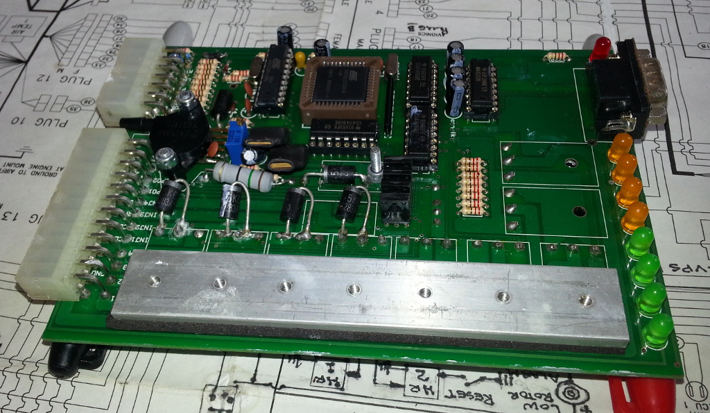
Pro-X Repair
The Pro-X ECU uses a standard 2-layer printed circuit board with through-hole components. All of the integrated circuits are installed in sockets. While sockets make the IC chips easily replaceable, they introduce a much higher probability of failure due to corrosion of the pins or the ICs simply falling from the sockets.
All of the components for this ECU are still easily available. There are 2 processors on the board with embedded firmware code. I didn't verify yet whether the firmware code has been "locked" in the processors. If it's not locked, then it would be possible to replace these processors if required and re-flash the firmware code. Otherwise the processor chips would not be replaceable.
Basically, these ECUs are relatively easy to repair.
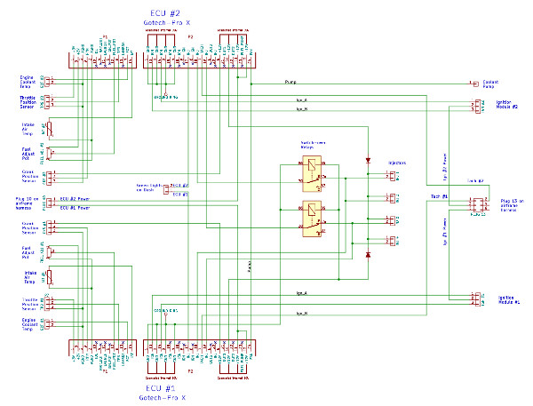
VP Engine Wiring Harness
Pro-X Programming
The fuel tables, ignition tables and parameter tables are stored in flash memory, and are programmable from a computer. Programming is done over a serial RS-232 link and does not require a special communication interface or programmer.
A software app to edit the fuel tables, parameters, etc is available for download from GoTech-MFI.